
With the upcoming end-of-life for the VMware NSX Migration fo VMware Cloud Director that has been announced here the source code and all the released builds are now available publicly on Calsoft GitHub repository: https://github.com/Calsoft-Pvt-Ltd/NSX_V2T_Migration_Tool. Calsoft engineers were developing the tool from the beginning so they do have the expertese to maintain the code and support those service providers that have not been able yet to migrate. If you are such a provider I encourage you to contact Calsoft: techsupport@calsoftinc.com.
Author: Tomas Fojta
VMware Cloud Director In-place Migration from NSX-V to NSX-T
VMware NSX Migration for VMware Cloud Director is a tool that automates migration of NSX-V backed Org VDCs to NSX-T backed provider VDC (PVDC). It is a side-by-side migration that requires standing up a new NSX-T cluster(s) to accommodate the migration. I described the process in my older blog.
However, there might be a situation that prevents this approach – either because hardware is not available or because only one cluster is available (VCD on top of VMware Cloud Foundation management domain).
We have derived and tested a procedure that enables in-place migration for such corner cases. It is not simple and requires the concurrent usage of NSX Migration Coordinator and NSX Migration for VCD. It also has some limitations but it can be an option when the regular side-by-site migration is not possible.
High Level Overview
At a high level the procedure is from VCD perspective still side by side and uses NSX Migration for VCD, but both source PVDC and target PVDC reside on the same cluster (with resource pool backing) while NSX Migration Coordinator is converting individual hosts from NSX-V to NSX-T and temporarily bridging VXLAN and Geneve networks.
Here are the high level steps:
- Make sure the source PVDC (NSX-V backed) has vSphere resource pool backing (instead of whole cluster). Also make sure VCD version is at least 10.4.2.2.
- Partially prepare target NSX-T Environment (deploy Managers and Edge Nodes)
- If load balancing is used, also partially prepare NSX ALB (deploy Controllers and configure NSX-T Cloud and Service Engine Groups)
- Create target PVDC NSX-T with resource pool backing on the same cluster
- Migrate network topology of all Org VDCs using the cluster with the NSX Migration for VCD (while using identical VNIs for the Geneve backed networks)
- Convert cluster ESXi hosts from NSX-V to T and migrate workloads to Geneve backed networks with NSX Migration Coordinator
- Migrate Org VDC network services with NSX Migration for VCD
- Migrate vApps with NSX Migration for VCD
- Clean up source Org VDCs with NSX Migration for VCD
- Clean up NSX-V from VCD and vCenter
Detailed Migration Steps
PVDC backing with Resource Pools
The source PVDC must be backed by resource pool (RP) otherwise we will not be able to create another PVDC on the same cluster. If the PVDC is using the whole cluster (its root RP) then it must be converted. The conversion is not so difficult but requires DB edit, therefore GSS support is recommended:
- Create a child RP under the vSphere cluster to be used as a PVDC RP.
- Move all PVDC child RPs (that were under the cluster directly, including System vDC RP) under this new RP.
- Note down the VC moref of this new RP.
- Update VCD vc_computehub and prov_vdc tables in VCD database to point the rp_moref to this new RP moref from VC (step 3).
If necessary, upgrade VCD to version 10.4.2.2 or newer.
Prepare NSX-T Environment
- Deploy NSX-T Managers
- Deploy NSX-T Edge Nodes. Note that the Edge node transport zone underlay (transport) VLAN must be routable with the existing VXLAN underlay (transport) VLAN (or it must be the same VLAN). The ESXi hosts when converted by NSX Migration Coordinator will reuse the VXLAN transport VLAN for its TEP underlay.
- Make sure that Geneve overlay ID VNI Pool interval contains the VXLAN VNIs used in NSX-V


- Create overlay transport zone
- Register NSX-T manager to VCD
- Register VC as Compute Manager in NSX-T Manager
- Create Geneve backed network pool in VCD (utilizing transport zone from step #4)
- Create Tier-0 and VRF gateways as necessary based on your desired target topology
- Create provider gateways in VCD using Tier-0 or VRF GWs created in step #8
Prepare NSX ALB Environment (optional)
This step is necessary only if load balancing is used.
- Deploy Avi Controllers and import the Avi Controller Cluster into VCD
- Prepare management segment and Tier-1 GW for Avi NSX-T Cloud
- Set up NSX-T Cloud in Avi and import it into VCD. Note that the Avi Controller will indicate the NSX-T Cloud is in red state as there are no NSX-T backed ESXi hosts in the environment yet.
- Set up Service Engine Groups as necessary and import them into VCD
Create Target Provider VDC
- In vCenter create sibling resource pool next to the RP backing the source PVDC
2. In VCD create the target NSX-T backed PVDC backed by the RP created in step #1 while using the Geneve backed network pool created previously. Yes it is possible this way to create NSX-T backed PVDC on NSX-V prepared cluster.

Topology Migration
With NSX Migration for VCD perform prechecks for all Org VDCs using the cluster. Skip bridging assessment as it is not necessary.
vcdNSXMigrator.exe –filepath=sampleuserinput.yml –passwordFile=passfile –preCheck -s bridging
If there are no issues, process with creation of target Org VDC network topology again for all Org VDCs on the cluster. In the input YAML file include CloneOverlayIds=TRUE line which will ensure that target networks use the same Overlay IDs as the source networks. This will allow Migration Coordinator associate the right networks.
If the topology includes direct VLAN backed Org VDC networks then also use LegacyDirectNetworks=TRUE. This statement will force NSX Migration for VCD to reuse the existing DVS portgroup backed external networks in the target Org VDCs. You also need to make sure that each such parent external network is used more than just one Org VDC network (for example via a dummy temporary Org VDC), otherwise the migration would be using the “Imported NSX-T Segment” mechanism which would not work as there is no ESXi host available yet that could access NSX-T Segment. See below table from the official doc:

The topology migration is triggered with the following command (must be run for each Org VDC):
vcdNSXMigrator.exe –filepath=sampleuserinput.yml –passwordFile=passfile -e topology
At this stage workloads are still running on NSX-V prepared hosts and are connected to VXLAN/VLAN backed port groups. The target Org VDCs are created and their network topology (Edge GWs and networks) exists only on Edge Transport Nodes as none of the resource ESXi hosts are yet prepared for NSX-T.
Note that you should not use Edge subinterface connection on source Org VDCs networks as it will not work later with Migration Coordinator. Also note that distributed routed networks on source side will experience extended downtime during migration as Migration Coordinator bridging will not work for them. You can convert them to direct interface Edge connectivity or alternatively accept the downtime.
Routed vApps (that use vApp Edge) should be powered off (undeployed). This is because vApp networks are not migrated during topology migration and thus will not exist during the Migration Coordinator step.
Migration Coordinator
In this step we will convert NSX-V hosts to NSX-T. This is done with NSX Migration Coordinator which will sequentially put each ESXi host into maintenance mode, evacuate the VMs (and connect them to VXLAN or Geneve networks) to other hosts. Then it will uninstall NSX-V and install NSX-T vibs on the host and bridge VXLAN and Geneve overlays directly in VMkernel.
When done, from vCenter perspective workloads will end up on the target networks but from VCD perspective they are still running in the source Org VDCs! The routing and other network services will still be performed by source Edge Gateways. In order to later migrate network services to NSX-T Tier-1 GWs, we must make sure that source Edge Service Gateway VMs stay on NSX-V prepared host so they are still manageable by NSX-V Manager (which uses ESXi host VIX/message bus communication). This is accomplished by creating vCenter DRS affinity groups.
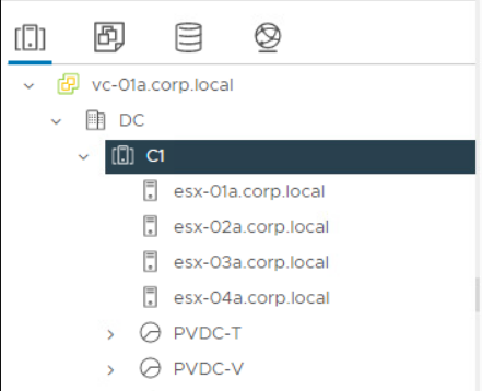
- Create DRS host group named EdgeHost that contains the last host in the cluster
- Create DRS host group named WorkloadHosts that contains all other hosts in the cluster
- Create DRS VM group named EdgeVMs that contains all ESG VMs
- Create DRS VM group named WorkloadVMs that containts all VCD managed workloads
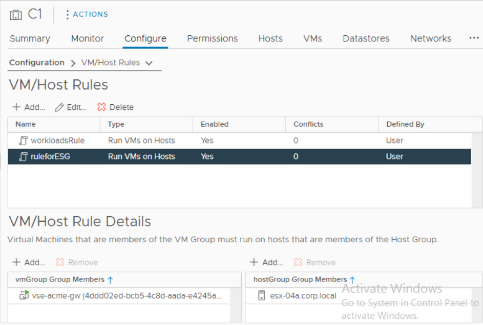
- Create DRS VM/Host must rule for all EdgeVMs to run on EdgeHost
- Create DRS VM/Host must rule for all WorkloadVMs to run on Workload hosts
- Make sure that DRS vMotions all VMs as required (if you are using ESGs in HA configuration disable antiaffinity on them).
Now we can start the Migration Coordinator conversion:
8. Enable Migration Coordinator on one of the NSX-T Manager Appliances via CLI command start service migration-coordinator

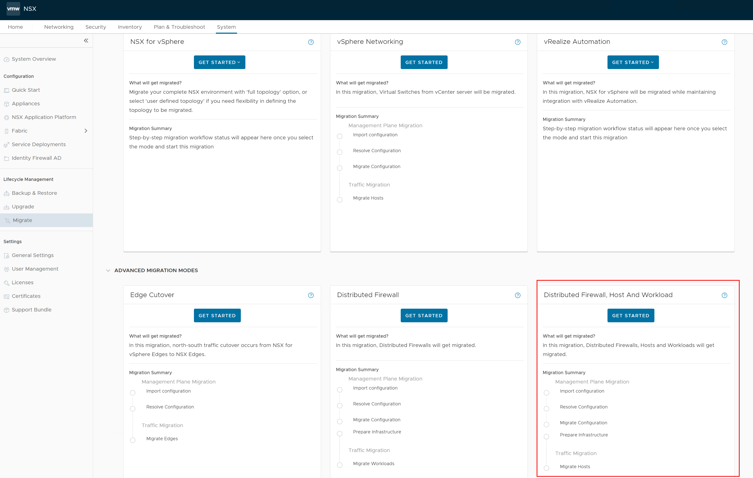
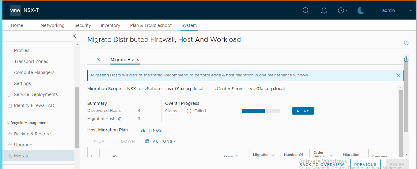
9. Access the NSX-T appliance via web UI and go to System > Lifecycle Management > Migrate and select the Advanced Migration mode DFW, Host and Workload.
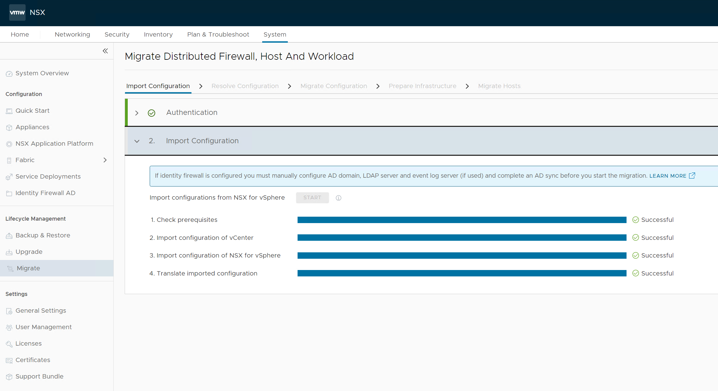
- Import the source NSX-V configuration by connecting the vCenter and providing NSX-V credentials:

- Continue to resolving configuration issues. Accept the recommendations provided by the Migration Coordinator.
Note: The Migration Coordinator does not recognize the topology created by VCD hence there may be unknown objects like security groups in case DFW is used in VCD. We accept all the recommendations by the Migration Coordinator which is to skip the DFW rules migration. Not to worry, DFW will be migrated by NSX Migration for VCD in a later step. - Next we migrate configuration:


- Prepare infrastructure in the next step:

- And finally we arrive at Migrate Host step where the conversion of each ESXi host is performed. Make sure the ESG designated host is last in the sequence. Note that there is no rollback from this step on. So make sure you have tested this process in lab environment and you know what you are doing.

Either use Pause in between host option or let the migration run until the last host conversion. We will pause there (or cancel the VC action that tries unsuccessfully to put the ESG designated host into maintenance mode as there are DRS pinned VMs on it.

Network Services Migration and VCD vApp Reconciliation
Next, we need to migrate network services from NSX-V ESGs to Tier-1 GWs, migrate DFW and finally from VCD perspective migrate vApps to target Org VDCs.
For each Org VDC perform network services migration:
vcdNSXMigrator.exe –filepath=sampleuserinput.yml –passwordFile=passfile -e services
N/S network disconnection will be performed. NSX-V Edge Gateways will be disconnected from external networks. Source Org VDC networks will be disconnected from their NSX-V Edge Gateways and target Org VDC networks will be connected to NSX-T Tier-1 GWs and Tier-1 GWs will be connected to Tier-0 gateway. If LB is used the Service Engine deployment will happen during the phase automatically by Avi Controller.
For each Org VDC perform vApp migration step:
vcdNSXMigrator.exe –filepath=sampleuserinput.yml –passwordFile=passfile -e movevapp
Clean-up Phase
- Clean up all source Org VDCs with:
vcdNSXMigrator.exe –filepath=sampleuserinput.yml –passwordFile=passfile –cleanup - As the previous step deleted all NSX-V ESGs we can go back to NSX Migration Coordinator and convert the remaining host to NSX-T. We can also remove all DRS rules that we created for ESGs and VCD Workloads.

- Disable and remove source Provider VDC.
- In case there are no more NSX-V backed provider VDCs in the environment remove VXLAN network pools and unregister NSX-V from VCD as described here.
- If you migrated your last NSX-V cluster perform NSX-V cleanup from vSphere as described here: https://docs.vmware.com/en/VMware-NSX-T-Data-Center/3.2/migration/GUID-7A07429B-0576-43D0-8808-77FA7189F4AE.html
How to Scale Up NSX Advanced Load Balancer Cloud In VCD?
VMware Cloud Director relies on NSX Advanced Load Balancer (Avi) integration to offer load balancing as a service to tenants – more on that here. This article discusses a particular workaround to scale above the current NSX-ALB NSX-T Cloud limits which are 128 Tier-1 objects per NSX-T Cloud and 300 Tier-1 objects per Avi Controller cluster. As you can have up to 1000 Tier-1 objects in single NSX-T instance could we have load balancing service on each of them?
Yes, but let’s first recap the integration facts.
- VCD integrates with NSX-T via registration of NSX-T Managers
- The next step is creation of VCD Network Pool by mapping it to Geneve Transport Zone provided by the above NSX-T Managers
- Individual Org VDCs consume NSX-T resources for network creation based on assigned VCD Network Pool
- VCD integrates with NSX ALB via registration of Avi Controller Cluster
- NSX ALB integrates with NSX-T via NSX-T Cloud construct that is defined by NSX-T Manager, Overlay Transport Zone and vCenter Server
- NSX-T Cloud is imported into VCD and matched with an existing Network Pool based on the same NSX-T Manager/Overlay Transport Zone combination
- Service Engine Groups are imported from available NSX-T Clouds to be used as templates for resources to run tenant consumed LB services and are assigned to Edge Gateways
Until VCD version 10.4.2 you could map only single NSX-T Cloud to a Geneve Network Pool. However with VCD 10.5 and 10.4.2.2 and newer you can map multiple NSX-T Clouds to the same Geneve Network Pool (even coming from different Avi Controller clusters). This essentially allows you to have more than 128 Tier-1 load balancing enabled GWs per such Network Pool and with multiple NSX ALB instances could scale all the way to 1000 Tier-1 GWs.

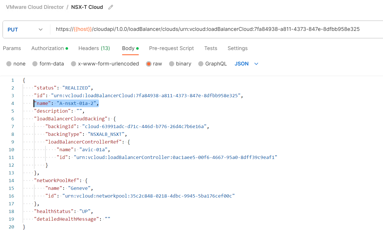
The issue is that VCD currently is not smart enough to pick the most suitable NSX-T Cloud for placement from capacity perspective. The only logic VCD is using is the priorization based on the alphabetic ordering of NSX-T Clouds in the list. So it is up to the service provider to make sure that on top is the NSX-T Cloud with the most available capacity.

As can be seen above I used A- and B- prefixed names to change the prioritization. Note that the UI does not allow the name edit, API PUT call must be used instead.
Note: The assignable Service Engine Groups depend if the Edge Gateway (Tier-1) has already been assigned to a particular NSX-T Cloud or not. So the API endpoint will reflect that:
https://{{host}}/cloudapi/1.0.0/loadBalancer/serviceEngineGroups?filter=(_context==<gateway URN>;_context==assignable)
Lastly I want to state that the above is considered a workaround and a better capacity management will be address in the future VCD releases.
What Are VMware Cloud Director Three Personas?
Introduction
Warning: Alpha/experimental feature content follows
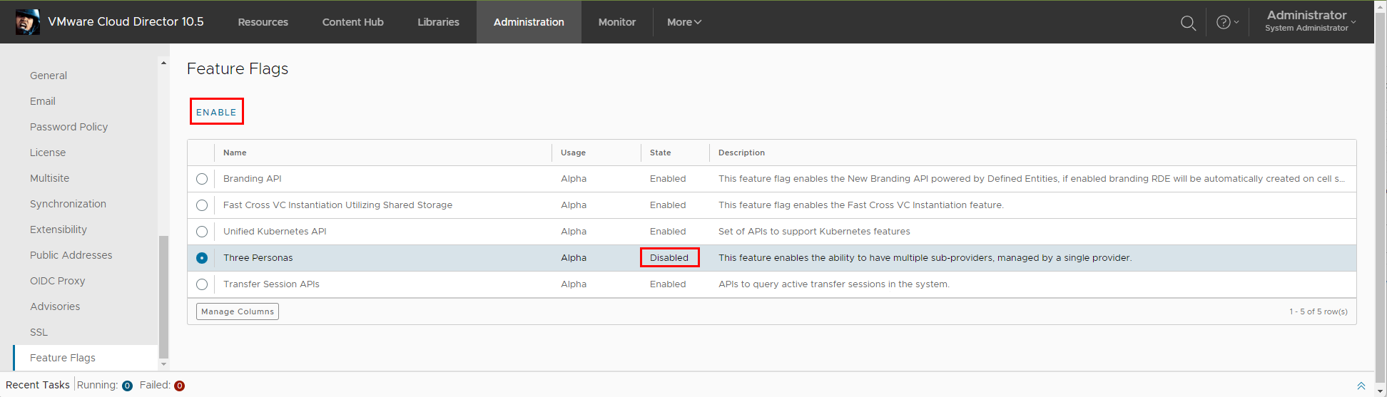
If you have installed VMware Cloud Director 10.5 you might have noticed a new disabled Feature Flag functionality called Three Personas. This is a preview of new capability that will be iteratively added to VCD in upcoming releases. However you can already use some of it today after enabling the feature flag.
This new feature creates ability to create sub-provider like organizations that have the right to manage other organizations while not having the full VCD system admin rights. In this first iteration the sub-provider cannot create such organizations or add them any resources, but can operate within their context on their behalf. While this is just scratching the surface of things to come, this already covers some use cases that were requested by many service providers. Namely the ability to enpower provider support team to manage certain tenant level operations in a subset of organizations without the ability to access the infrastructure related objects that only system admins should manage (PVDCs, Provider Gateways, VCs, …)
How to Get Started
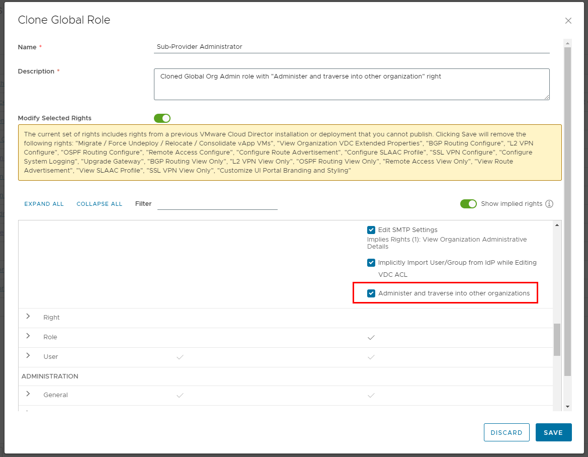
After you enable the feature flag you will notice a new Default Sub-Provider Entitlement right bundle is created with new right Access Control: Organization: Administer and traverse into other organizations.

We need to create new global role “Sub-Provider Administrator” that we will clone from the Global Organization Administrator and add this new additional right to it.
Now we can create the Sub-Provider organization. We use the regular New Organization UI workflow. However notice we can see new Enable sub-provider option. When selected the Default Sub-Provider right bundle is automatically assigned to this organization.

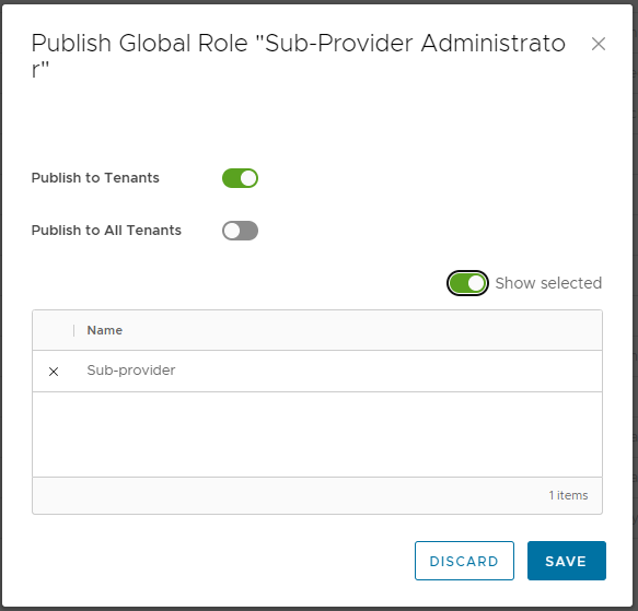
We will publish the new Sub-provider Administrator global role to this organization.
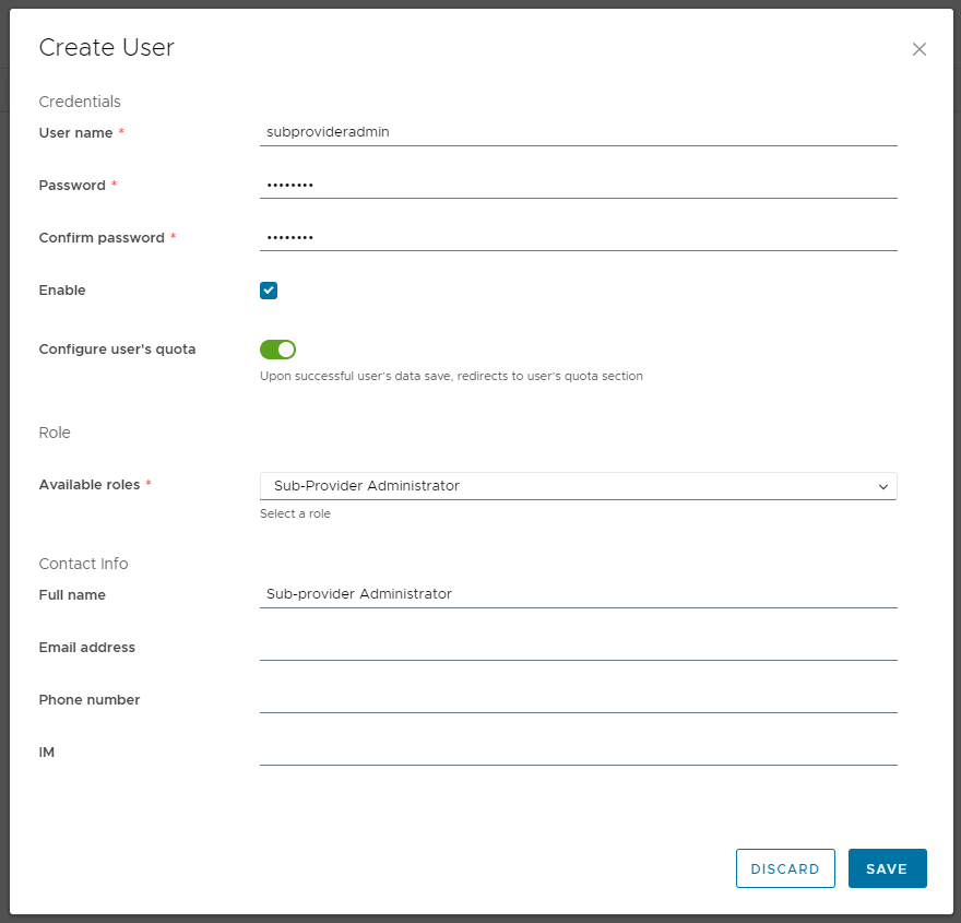
Now you can create some users in this Sub-provider organization and assign them the new global role.
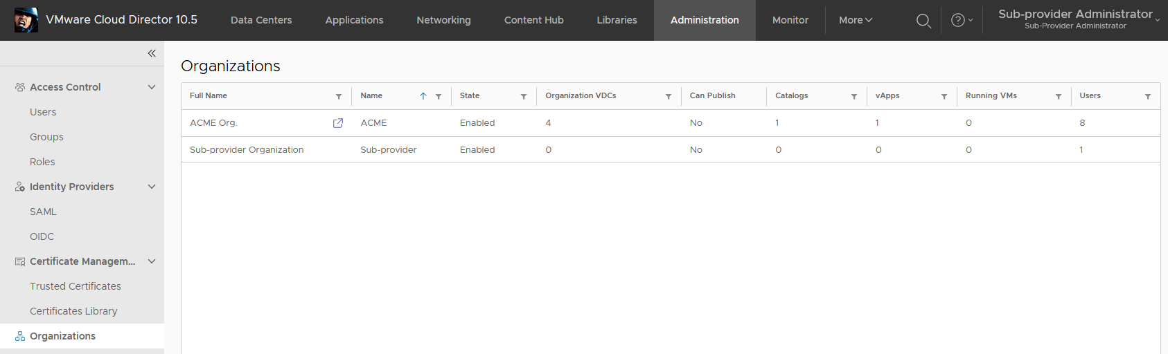
Now we can log in into the Sub-provider organization and can see that in the Administration > Organizations we see only our own organization.

This is because we have not yet been entitled to see other specific organizations. This step currently in VCD 10.5 requires API usage.
While logged in as system admin with the API version 39.0.0-alpha run the GET Org OpenAPI call on the organization you want to manage (ACME Org. in my case) as the sub-provider. Notice the new managedBy section in the output JSON.
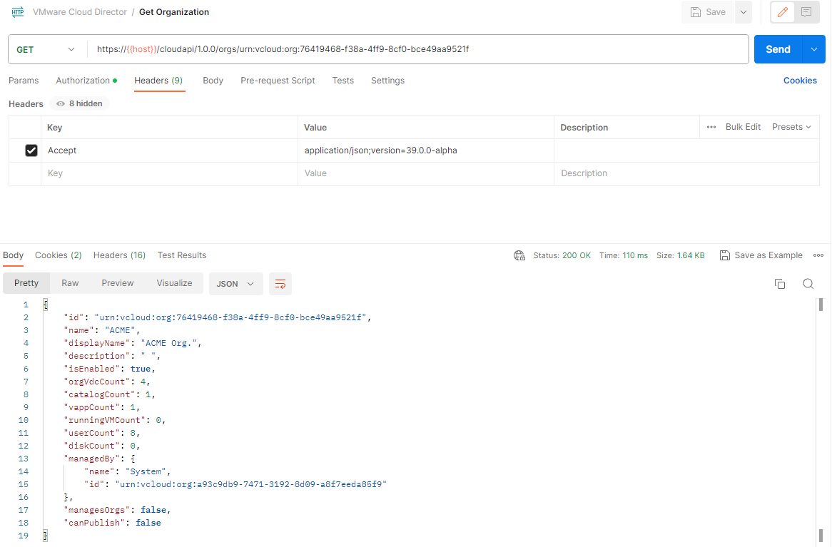
By default every org is managed by System org. We will change it to our Sub-provider org and use PUT on the same Org endpoint.

You can immediately see in the Sub-provider Org UI that the ACME Org is accessible and we can traverse to it.
ACME Org in the sub-provider context.

Any tasks performed or objects created in the ACME Org within the sub-provider context will by marked/owned by SYSTEM.
Legacy API Login Endpoint Removed in VCD 10.5
A brief heads up note that with the release of VMware Cloud Director 10.5 and its corresponding API version 38.0 the legacy API endpoint POST /api/sessions has been removed.

It has been announced for deprecation for some time (actually it was initially planned to be removed in VCD 10.4) and I blogged in detail about the replacement /cloudapi/1.0.0/sessions and /cloudapi/1.0.0/sessions/provider endpoints in the Control System Admin Access blog post.
Any 3rd party tools that use the legacy endpoint and API version 38.0 will get HTTP response 405 – Method not found.
Note that the GET /api/session method will still work until all legacy APIs will be moved to /cloudapi.
Also due to backward compatibility API versions 37.2 – 35.2 still provide the legacy endpoint even with VCD 10.5.
